Use a flanged bushing when you need radial + moderate axial in a compact part. For high axial or serviceable stacks, a separate thrust washer is easier to replace and size.
Industry Insights
Industry Insights
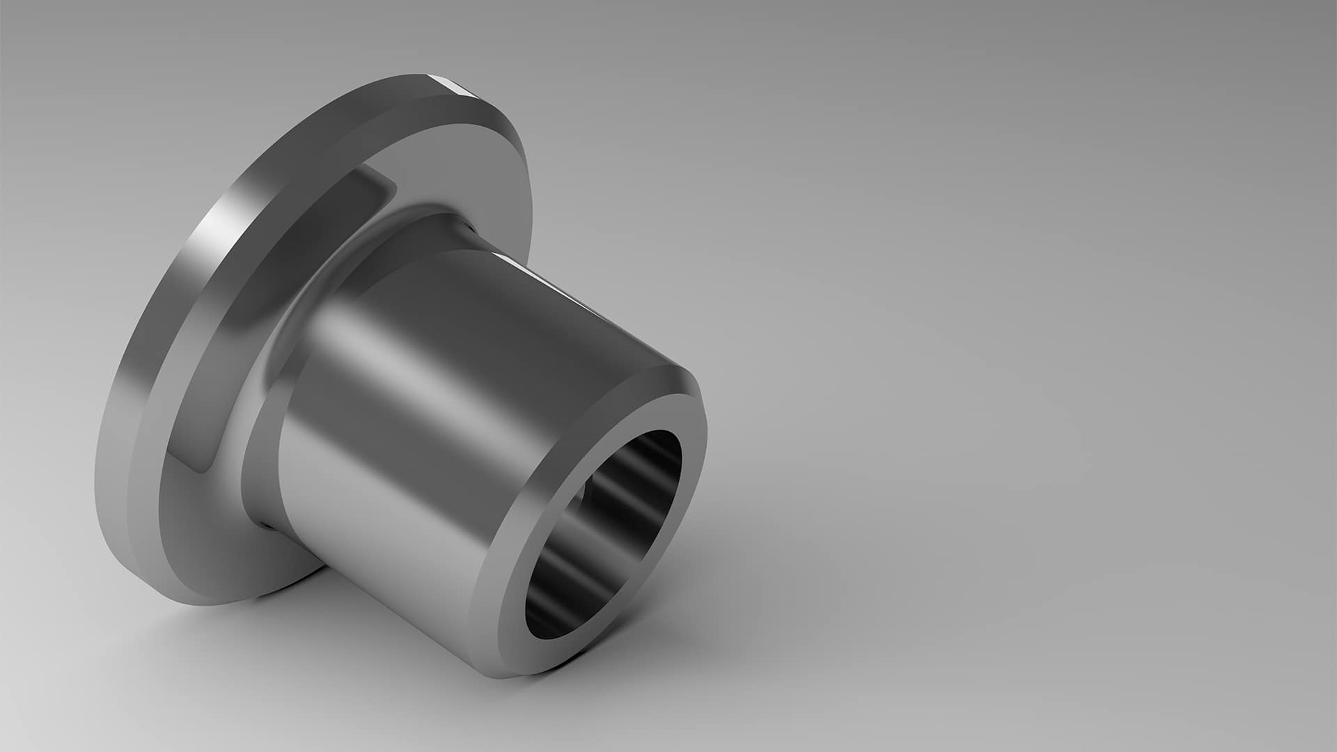
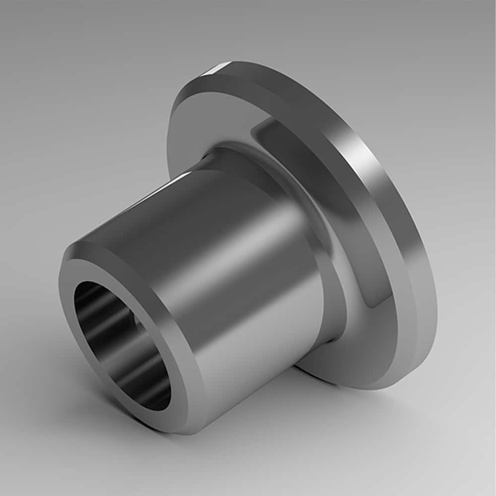
Thrust & Flanged Bushing (radial + rod ends)
Selection, Failures, Fixes & Coatings
What Are Thrust & Flanged Bushings?
Thrust bushings (thrust washers) carry axial load between faces.
Flanged bushings are sleeve bushings with an integral flange that locates the bushing and/or
shares axial load while the cylindrical ID still supports radial load on the shaft.
They run in boundary/mixed lubrication much of the time; life depends on PV, materials, clearance, and surface finish.
Typical uses: linkages with end thrust, stop faces, indexing tables, actuators with axial reaction,
hinges and door mechanisms, conveyors (end thrust), packaging & food equipment (washdown), marine and outdoor hardware.
Selection Cheatsheet (Duty, PV, Geometry, Environment)
- Mostly axial load? Thrust washer or flanged bushing with adequate flange area; verify face pressure and torque.
- Combined load? Flanged bushing handles radial via ID and axial at flange; confirm both PV (ID) and face pressure (flange).
- Oscillation/start-stop? Favor PTFE/composite liners or polymers tuned for boundary regime.
- Sustained rotation? Use oil feed and groove pattern that doesn’t starve the loaded arc; consider bronze/babbitt.
- Environment drives materials: washdown → stainless + inert coatings; abrasive → hard low-roughness surfaces + seals.
- After coatings: re-measure ID/OD, flange thickness & flatness, face runout, and hot clearance.
Environment → Attributes Matrix
| Environment | Material / Surface | Clearance / Flatness | Fits (shaft / housing) | Sealing | Lubrication |
|---|---|---|---|---|---|
| Oscillating hinge with end thrust | PTFE/composite liner; hard chrome on pin & flange face | Nominal clearance; flange flatness critical for smooth torque | Pin h6–h9 / Housing H7 with OD interference to prevent spin | Deflectors or boots | Grease purge schedule; compatible with liner |
| Indexing table axial stop | Bronze/babbitt thrust washer; ground face; optional chrome | Face flatness/parallelism; runout <= torque spec | Clamped stack; anti-rotation features | Non-contact shields; chip guards | Oil feed or high-quality grease for stop impacts |
| Washdown / Food | Stainless shells; inert chrome or Ni-P on faces & pins | C3-like looseness concept if thermal rise; verify torque hot | k5–m6 / H7; confirm post-coat ID & flange thickness | Contact seals + deflectors; avoid jets at faces | H1 grease; purge after wash; dry-out routine |
| Dusty / Abrasive | Hard, low-roughness shaft & face coatings; wear-tolerant liners | Don’t over-tighten; allow film | Secure fits; add anti-rotation notch if needed | Labyrinth + shields; purge paths | Grease with sealing behavior; set purge interval |
| High temperature | High-temp polymers/composites or bronze/babbitt | Clearance for thermal growth; face flatness maintained hot | Thermal growth model for fits/clamp | Heat shields / non-contact seals | High VI oil or dry-film compatible liner |
Common Failures & Diagnostics
Rapid Triage

1) Thrust Face Wear / Grooving
Symptoms
Rising axial play, scratch rings on face, torque fluctuations.
Likely causes
Abrasive ingress, PV over limit, inadequate lubrication, face not flat/parallel.
Checks
Face flatness & runout; contamination paths; PV vs. catalog; groove design.
Non-coating actions
Improve sealing/guards; adjust grease/oil; redesign grooves; reduce load or speed.
When surface treatments help
Hard, low-roughness chrome on face reduces abrasion once ingress is controlled.
2) Seizure / Scoring (ID or face)
Symptoms
Squeal, heat spike, visible scoring on shaft or face.
Likely causes
Clearance too tight hot, viscosity too low, misalignment, overload.
Checks
Hot clearance; viscosity @ temp; face parallelism; alignment.
Non-coating actions
Resize clearance; raise viscosity/cooling; correct alignment; add grooves.
When surface treatments help
Low-roughness chrome reduces adhesion after clearance/lube are correct.
3) Fretting at Flange Seat / OD
Symptoms
Reddish oxide at OD or under flange, creak/squeak, micro-motion marks.
Likely causes
Insufficient interference or clamp; vibration; thermal cycles.
Checks
Fit classes; clamp torque sequence; seat finish; transport profile.
Non-coating actions
Increase interference/anti-rotation features; improve clamp and seat flatness.
When surface treatments help
Micro-textured chrome on seats lowers adhesion once fits are corrected.
4) Flange Cupping / Extrusion
Symptoms
Edge-high contact, uneven wear ring, flange deformation.
Likely causes
Face not supported; clamp over-torque; thermal gradients; polymer creep.
Checks
Seat flatness; clamp distribution; temperature map; material choice.
Non-coating actions
Improve backing washer/seat; adjust clamp; choose stiffer material.
When surface treatments help
Not primary; geometry/support dominates.
5) Stick-Slip / High Breakaway Torque
Symptoms
Jerky axial starts, audible squeak, inconsistent positioning.
Likely causes
Boundary regime with high μs/μk; incompatible grease; rough faces.
Checks
Grease chemistry; face finish; temperature; groove pattern.
Non-coating actions
Change grease; polish faces; adjust preload or dwell profile.
When surface treatments help
Low-roughness chrome reduces μ variance after lube/grooves are corrected.
The Big Three: Corrosion, Lubricity, Dimensional Stability
Use coatings when they address surface-driven issues (corrosion, fretting, abrasion) on pins/shafts, faces, and housing seats. Coatings don’t replace clearance control, alignment, sealing, or lubricant choice.
| Concern | What it means | Non-coating controls (first) | When coatings help | Notes |
|---|---|---|---|---|
| Corrosion resistance | Protect faces, IDs/ODs, and pins from rust/chemicals | Seals/deflectors; wash angles; drying; compatible H1 grease | Thin dense/micro-cracked chrome or Ni-P on faces & pins | Re-measure ID and face flatness after processing |
| Lubricity | Reduce stick-slip under axial load and oscillation | Right grease/oil; groove design; PV within material limits | Low-roughness/micro-textured chrome on pins & faces | Coatings complement—don’t replace lubrication discipline |
| Dimensional stability | Keep clearance, flange thickness, and face runout in spec | Thermal model; rigid seats; correct clamp sequence | Controlled-thickness coatings; post-coat metrology | Small thickness shifts change torque & axial play |
Fits, Geometry & Axial Location (Quick Rules)
-
Pin/shaft fit: sliding fit for motion (e.g., h6–h9 vs. bushing ID). Finish Ra ≤ ~0.2–0.4 μm for liners.
-
OD/seat: prevent spin/fretting—use interference or anti-rotation features; seat flatness matters under the flange.
-
Flange face: perpendicular to bore; adequate thickness; support with a flat backing surface to avoid cupping.
-
Grooves & chamfers: add grease/oil pockets without starving loaded arc; chamfers clear shaft radii.
-
After coatings/linings: ream/hone to size; re-measure ID, flange thickness, face runout, and hot clearance.
Checklist
-
Seat flatness/parallelism verified
-
Hot clearance modeled/checked
-
Face runout & torque within spec
-
Post-process metrology complete
Frequently Asked Questions
Within its face area and material PV limit—verify face pressure and torque. For heavy axial duty, consider a dedicated thrust washer/bearing.
Only liners designed for dry running should run dry. Bronze/babbitt needs grease/oil; polymers vary—check the catalog.
Yes. Control thickness, then ream/hone IDs and re-measure flange thickness and face runout after coating.
Use proper OD interference, knurls/serrations, flats, or anti-rotation tabs; confirm clamp sequence.
Case Snapshots
- Indexing stop face wear — Bronze thrust washer grooved after packaging dust ingress.
Actions: added deflectors, switched to micro-textured hard chrome face + filtered oil feed; verified runout.
Outcome: torque stabilized; no new grooves after 6 weeks. - Washdown hinge stick-slip — PTFE-lined flanged bush squealed after sanitation cycles.
Actions: hard-chrome pins + H1 grease purge; added boots; validated cleaner pH; rechecked flange flatness.
Outcome: smooth start torque; reduced staining through audit period.
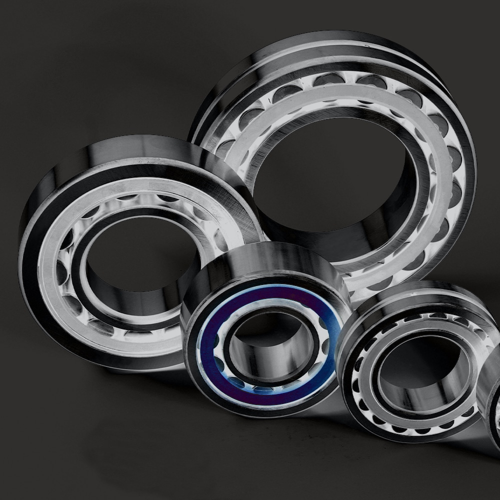
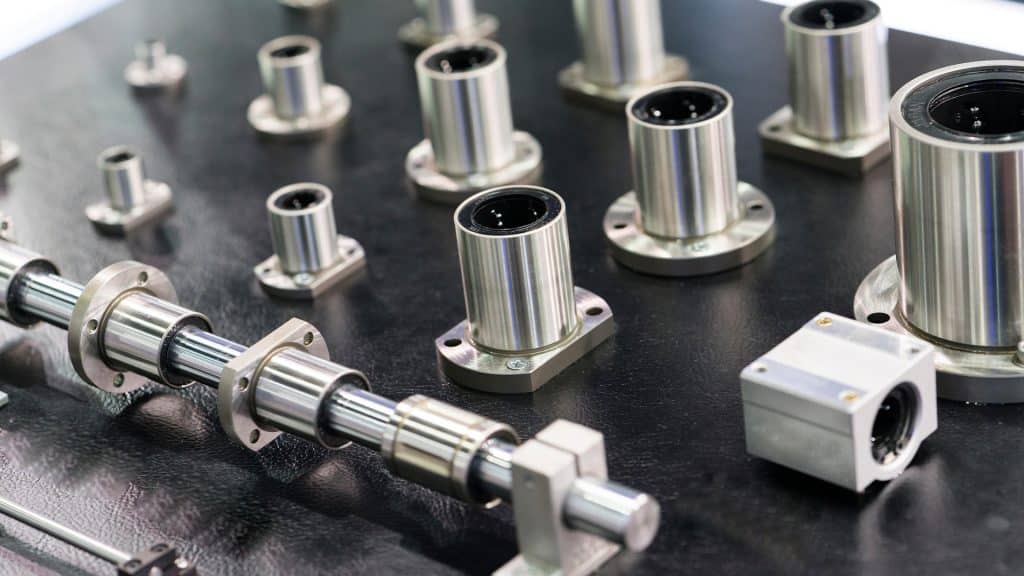
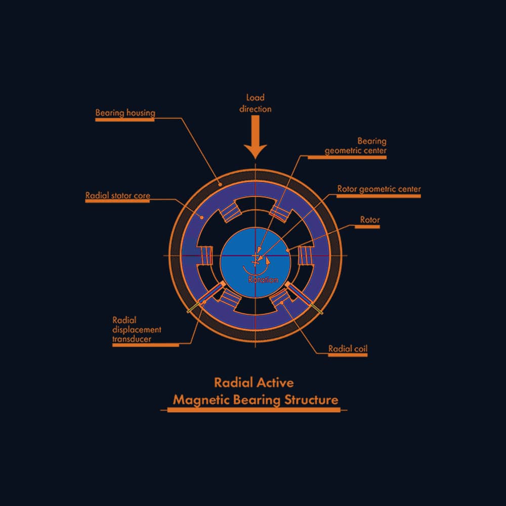
Other Bearing Types
Different bearing designs manage radial loads, axial loads, speed, and misalignment in different ways.
Compare other bearing types to better understand load handling, common failure modes, and application fit.

Have a failure photo, sound clip, or spec?
Upload it for a no‑fluff diagnostic checklist. We’ll map symptoms → checks → next actions (and only propose coatings when they’re truly indicated).