What is Wear?
When mechanical parts and assemblies fail, it usually happens by fracture, corrosion or wear. Many observers certainly understand wear the least among the three. However, its importance in medical applications is undeniable. Individuals often assume that wear and friction are the same, but reducing friction does not necessarily reduce wear. Limited experience has caused some to maintain, that a direct relationship exists between higher hardness and lower wear. However, large-scale testing on a variety of materials shows that these are two distinct properties. Wear and friction are different.
Wear is material loss and deformation at contact surfaces, and results in particle generation and surface degradation. Reducing the wear of surgical instruments lowers the production of wear particles and the possibility of introducing foreign matter into the body. Extended instrument life and consistent performance are other benefits of considering wear in instrument design. Many types of wear have been observed and classified as shown below.
- Adhesive Wear
- Oxidative wear
- Metallic wear
- Galling/ Seizing
- Abrasive Wear
- Low-stress scratching abrasion
- High-stress grinding abrasion
- Gouging abrasion
- Erosion
- Erosion
- Cavitation
- Particle impingement
- Fretting
- Fretting corrosion
- False brinelling
- Friction oxidation
- Chafing fatigue
- Wear oxidation
Adhesive Wear
Adhesive wear is a common form of metal loss. In surgical instrument applications, adhesive wear and galling are the most usual forms of wear. This occurs when no outside abrasives are present between the two wear surfaces. At low loads, an oxide film usually forms on the contact surfaces. This prevents metallic bonding between the mating materials, resulting in a low rate of wear referred to as oxidative or mild wear.
As loads are increased a transition is reached. The oxide film breaks down and metallic bonding (cold welding) takes place between the two surfaces. This is referred to as severe metallic wear. It results in rapid material loss and wear particle generation.
Galling is a special case of severe adhesive wear. The wear particles can no longer be accommodated by the surface roughness and contact clearances. At this point, the contact surfaces become cold welded. Further movement causes the surface metal to deform and tear. In an extreme case, metal seizure occurs. When contact pressures are high, galling and seizure can occur with minimal amounts of sliding (less than one revolution or fractions of an inch).
Abrasive Wear
Abrasion occurs when a hard material scratches or gouges the surface of a softer material. The abrasive material may be one of the sliding surfaces or particles between the two surfaces. When the contact stress are too low to crush the abrasive particles, the cutting action is defined as low-stress scratching abrasion. This usually results in surface scratches with little sub-surface deformation.
In high-stress grinding abrasion, the loads are great enough to crush the abrasive material. This usually causes permanent plastic deformation of the base metal along with material removal. Gouging abrasion occurs when high stresses create significantly large grooves on the contact surfaces.
Erosion
Erosion is material loss from the abrasive action of moving fluids on a component. High pressure liquid streams can even be used to perform rapid machining operations.
Components that experience large pressure changes and turbulent flow can wear due to cavitation erosion. Cavitation is the formation and collapse of numerous small bubbles during turbulent flow. The ultrasonic shock of the collapsing bubbles scrubs the metal surface. This can cause long term surface loss.
Fluid valves and pumps are examples of application where cavitation may occur. Surface destruction is accelerated by the presence of solid particles within a fluid stream.
Wear caused by suspended solid particles is referred to as impingement erosion. Material resistance to impingement erosion varies with the angle of particle impingement and material hardness.
Fretting
Fretting is material loss that occurs between tight-fitting surfaces that are subject to vibrational movements (such as riveted, other fastened joints and electrical connections). Material loss is from a combination of oxidative and abrasive wear. The oscillation of the two surfaces causes the formation of oxide films that are then abraded away by oxidized wear debris. The affected surfaces sometimes look as if they were mechanically deformed, so this wear is sometimes called false brinelling. It is also referred to as fretting corrosion, friction oxidation, chafing fatigue, and wear oxidation.
Wear Testing and Results
Tests are constantly being developed to measure the properties of materials. Some tests are designed to simulate actual use. These often use a large number of variables, such as speeds, loads and times. For example, one could make a surgical bone cutter out of all the available material options. Evaluators could then assess each cutter through a series of simulated performance tests. This method would certainly determine which of the materials is best suited for the particular application, but it usually incurs a substantial cost. The results of such a test may only be applicable to selecting materials for devices of similar design and use.
More general tests that measure characteristic properties tend to apply to a larger number of engineering design problems. This often allows a designer to rapidly narrow his selection to a few materials. One must use caution when applying general results to a specific design problem–unless the intended use is similar to the test configuration. Engineers must use even greater caution when applying results from simulated tests to different engineering problems.
Several tests have been used by industry for measuring wear and galling resistance of materials. Three popular ones for which data exists are ASTMG83 Standard Test Method for Wear Testing with a Crossed-Cylinder Apparatus (10), ASTM G98 Standard Test Method for Galling Resistance of Materials, and ASTM G99 Standard Test Method for Pin-on-Disk Wear Testing. A brief description of each of these tests with results are provided in the following text.
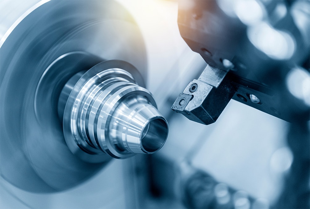
Crossed-Cylinder Wear Test, ASTM G83
For the crossed-cylinder test, ASTM G83, two cylindrical specimens are positioned perpendicular to each other in the test machine. Some commercially available machines have an optional force measuring system for determining coefficients of friction. The test equipment allows one specimen to rotate at speeds up to 400 rev/min. The second, nonrotating specimen presses against the moving specimen at a specified load by means of an arm and attached weights. Technicians typically grind sample surfaces to a finish of 16 microinches AA or less. The test duration and rotational speed are varied depending on which of three test procedures are specified. To determine the amount of wear, technicians weigh the specimens before and after the test. Researchers have reported results as weight loss, but they typically convert them to volume loss.
Results of Crossed-Cylinder Wear Test
Since the introduction of the crossed-cylinder test, many medically employed materials have been evaluated for wear compatibility. The wear resistance for both self-mated and dissimilar metal couples are presented in Figure 1 and again in Table 4. Lower bar heights on the graph indicate lower material losses and increased wear resistance. The test results show that significant reductions in wear can be realized through proper material selection. Additional wear reductions from 93% to 44% are attainable when ME-92 chromium composition coating is specified over regular 300 series, 400 series and precipitation hardening alloys. Applying a protective coating on common grades of stainless steels may also realize significant cost savings instead of using special alloys and proprietary materials.
WEAR RATE OF CORROSION-RESISTANCE COUPLES
Weight loss rates in mg/1,000 cycles
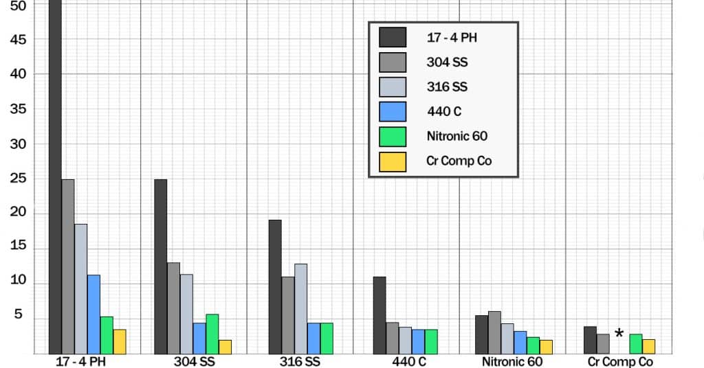
Figure 1. This composite graph compares the metal wear rates of various materials on themselves and each other material listed. Lower bar height on the graph is desirable, indicating lower material loss and lower wear rates. Significant wear reductions can be realized with proper materials selection and the ME-92® chromium composition coating.
Threshold Galling Stress Test, ASTM G98
In the “button and block” test, ASTM G98, the machinists create a small button and a large block sample with two flat surfaces finished to 10 to 45 microinches AA. The operator then compresses the couple together at a constant load using a hydraulic or screw feed press. Figure 2 presents the test arrangement. The operator slowly rotates one specimen one revolution relative to the other. The examiner then inspects the sliding surfaces for the appearance of torn metal, indicating galling. If galling does not occur, the tester uses new samples at higher loads until galling happens.
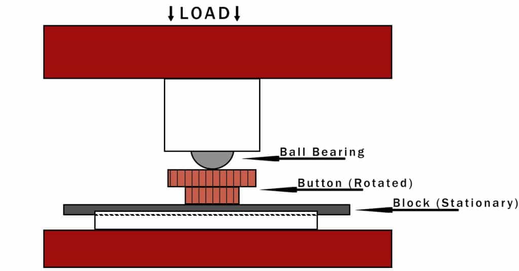
Figure 2. Schematic of “button-on-block” gall test arrangement
Results of Threshold Galling Test
The results of this test indicate that the increased hardness of 17-4 PH did not improve galling resistance over 300 series. Proper selection of mating materials allows instruments to operate at higher contact stresses without galling. Coating stainless steels with ME-92 achieved even greater galling resistance. Figure 3 and Table 5 graphically present the improved gall resistance of ME-92.
UNLUBRICATED THRESHOLD GALL STRESS, IN 1000 PSI
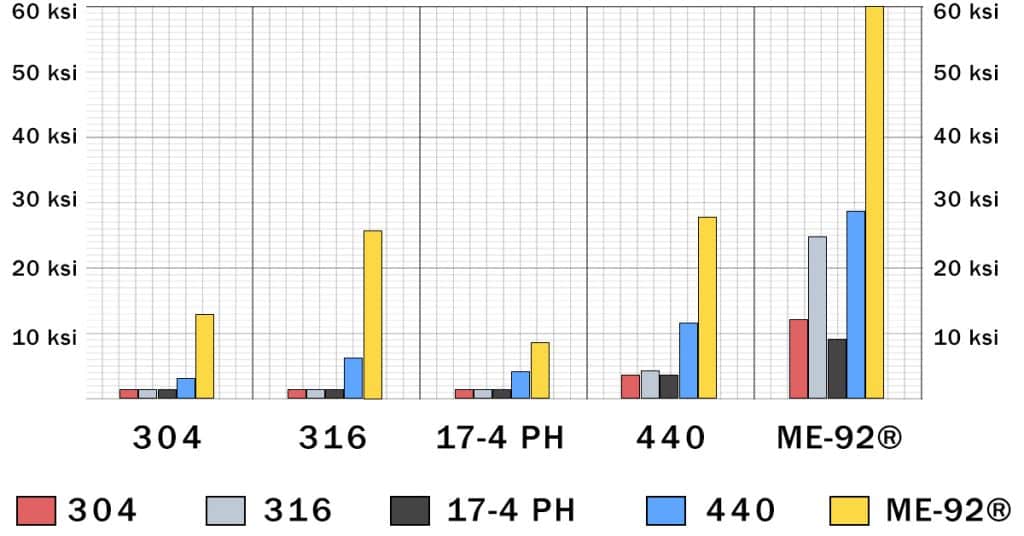
Figure 3. This graph compares the gall resistance of materials sliding on themselves and each other listed material. Higher bar readings are desirable, indicating greater resistance to galling and seizure. Stainless steels enhanced with ME-92® chromium composition coating, are significantly more gall resistant then bare unlubricated stainless steels.
Pin-On-Disk Test, ASTM G99
The pin-on-disk wear test, ASTM 399, requires two specimens. The tester positions a pin with a radius tip perpendicular to a flat disk. They often use a rigidly held ball as the pin specimen. The test machine rotates the disk at 60 to 600 rev/min. The wear path is a circle on the disk surface. Technicians typically use finishes of 32 microinches AA or less. They usually report test results as volume loss per cubic millimeter, plotting wear volume separately for the pin and disk. Results can be a view of the test arrangement sliding distance or friction vs. sliding distance. A top is presented in Figure 4.
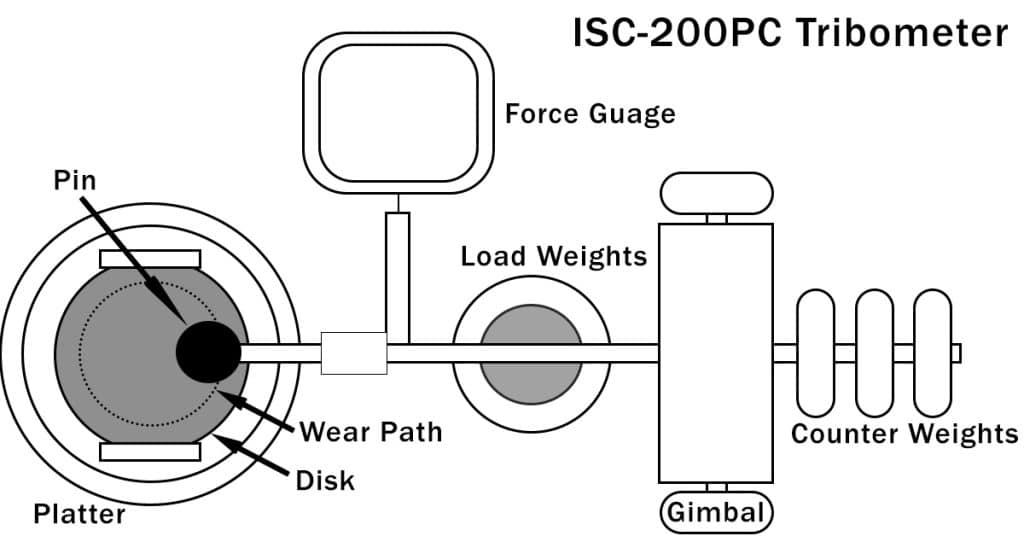
Figure 4. A top view of the test arrangement used for pin-on-disk wear test.
Results of Pin-On-Disk Tests
Pin-on-disk test results for three different material configurations are presented in Table 6. Wear was practically non-existent with the ME-92 coated samples compared to bare 17-4 PH.
This test not only gives wear information, but computerized systems can constantly monitor and plot friction values. The graph presented in Figure 5 gives friction coefficients vs. sliding distance. The uppermost jagged line, Test #1, is the couple 17-4 PH on 17-4 PH. Friction greatly increased with increasing sliding distance and operating time. The graph also shows large fluctuations in friction throughout the test. This is caused by wear and particle generation. A surgical instrument performing like this would have a jerky motion. The forces required to operate such an instrument could vary greatly during use.
The bottom plot presents the results of Test #3, where 17-4 PH runs on ME-92 coating. The total friction remained low and consistent compared to a bare stainless steel disk. The slight waiver in the plot is due to the “stick-slip” of surface irregularities on the softer 17-4 PH material. This may eventually result in higher wear than shown by the test.
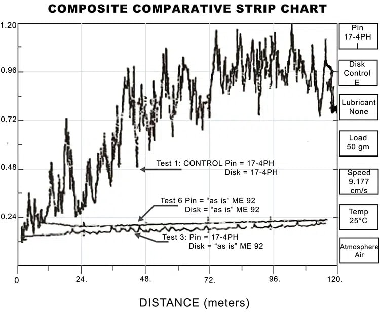
Figure 5. This graph presents plots of friction vs. sliding distance from pin-on-disk tests. The plots move up with increasing friction. Jagged movements of the 17-4 PH on 17-4 PH plot indicates that friction was fluctuating with use. Steady horizontal lines were obtained with use of the ME-92® coating, indicating low and consistent friction with use, and little material loss.
The Case for ME-92®
Even though the initial frictional values for the three configurations were very similar, friction for the bare 17-4 PH significantly increased as the testing continued. The most consistent frictional values were obtained when both components were coated with ME-92, as presented in the plot of Test #6. Neither wear nor particle generation was detectable when both surfaces were coated with ME-92. This series of tests demonstrates our earlier statements, that the initial friction measurement alone, is not a sufficient design criterion. One must consider how friction varies with time, for moving assemblies, to obtain desirable performance in the field.
Factors Affecting Wear
Several factors generally affect wear, including materials selection, friction, surface load, sliding distance, surface hardness, surface finish, and lubrication. Controlling the listed factors contributes to a successful application and the prevention of wear and premature failure.
Material Selection
We have seen from the previous test results that wear varies greatly depending on which materials you select. For critical applications, it is crucial that the person responsible for materials and process selection have adequate information and experience available to make a sound engineering decision. Carelessness in this area results in poor instrument performance and even field failures. The time and money spent in proper materials and process selection can be ten to a hundred-fold less expensive than field failures and product recalls.
Friction
We have seen from the previous test results that wear varies greatly depending on which materials you select. For critical applications, it is crucial that the person responsible for materials and process selection have adequate information and experience available to make a sound engineering decision. Carelessness in this area results in poor instrument performance and even field failures. The time and money spent in proper materials and process selection can be ten to a hundred-fold less expensive than field failures and product recalls.
Surface Load
Increasing the surface load between the sliding surfaces may cause a proportional increase in wear rates.
Sliding Distance
Increasing the sliding distance of an assembly causes a roughly proportional increase in material loss.
Surface Hardness
Wear resistance generally increases proportionally with increasing surface hardness (this may be very different from bulk hardness). Surface deformation during wear causes a localized increase in surface hardness on work-hardening metals. This explains why high-strain-hardening, austenitic stainless steels are more resistant to wearing down than harder precipitation hardened stainless steel.
Surface Finish
Surface finishes between 10 and 70 microinches (AA) offer similar wear resistance for many stainless steels. Very smooth surfaces promote cold welding (galling) due to high molecular interaction. High finishes also lack adequate clearance to store wear debris. Overly rough finishes increase wear by allowing surface asperities (irregularities) to become interlocked. This results in the “stick-slip” phenomena mentioned earlier. These surface irregularities begin to wear off when sliding occurs.
Lubrication
The use of lubrication is to prevent or reduce metal-to-metal contact and cold welding. Lubricants can also effectively reduce contact stresses. The type of lubrication and delivery system are important considerations for reducing wear and galling.
Coating suppliers design many surface modifications and coatings to perform as a “dry” lubricant. These can be useful when wet lubrication is not practical. Select and use properly.
Designing For Reduced Wear and Galling
We make the following design recommendations for reducing galling and wear with stainless steels.
- Select mating materials with adequate wear and galling resistance. In unlubricated systems or sporadically lubricated systems, materials selection becomes even more critical. Assemblies used in medical and surgical applications, generally lick adequate lubrication. Therefore, it is desirable to:
-
- Select materials with high threshold galling stresses for mating surfaces.
-
- Use dissimilar materials and/or those with differential hardnesses on the sliding surfaces (coating both surfaces with ME-92 is an exception to this rule).
-
- Select high work-hardening austenitic stainless steels for improved wear resistance (but not galling resistance) at temperatures below 350F.
-
- Select alloys for mechanical properties alone and apply surface modifications to obtain the desired resistance to metal failure modes.
- Lubricate where possible.
- Keep load, temperature, and speed as low as possible.
- Start with mated surfaces having a finish between 10 and 70 microinches (AA). Below 10 increases susceptibility to galling; above 70 increases wear.
- Increase contact area:
- to lower contact stress below threshold galling stress
-
- to lower the depth of wearing, by spreading the volume over a greater area
6. Specify acceptable dimensional tolerances, proper clearances and fits. Do not expect good material selection and lubrication to make up for poor mechanical design.
7. Consider the use of a reliable, resistant coating to extend the capabilities of bare contact materials.
Share on LinkedIn Share on Facebook