Yes. They protect the machine during power loss, trips, or startup/shutdown. Size them for touchdown energy and provide lubrication/heat paths.
Industry Insights
Industry Insights
Magnetic Bearings
Selection, Failures, Fixes & Coatings
What Are Magnetic Bearings?
Magnetic bearings support a rotor with magnetic forces—no physical contact in normal operation.
Active magnetic bearings (AMB) use electromagnets with closed-loop control (sensors + power amplifiers).
Passive designs use permanent magnets or diamagnetic/superconducting effects.
Hybrid systems often pair passive radial support with an active axial stage.
A backup (catcher) bearing carries the rotor during start/stop or faults.
Typical uses: high-speed compressors/blowers (oil-free air/process gas), expanders, vacuum pumps, flywheel energy storage,
turbo-molecular pumps, cleanroom tools, test spindles, cryogenic or caustic processes where no lube and cleanliness are critical.
Selection Cheatsheet (Duty, Air-Gap, Controls, Backup)
- Process & cleanliness: Pick AMB for oil-free/vacuum/clean gas. Validate materials vs. chemistry/temperature.
- Rotor dynamics: Confirm critical speeds, balance grade, and control stability margins (gain/phase) across operating range.
- Air-gap budget: Model thermal growth, bow, and assembly tolerances; preserve minimum gap at all conditions.
- Power strategy: UPS/ride-through needed for orderly rundown; define touchdown speed and energy on backup bearings.
- Controls & sensing: Redundant probes/channels where risk requires; EMI design; proper probe targets/surfaces.
- After coatings: Re-balance rotor; re-verify probe calibration, air-gap, and touchdown geometry; coatings must not perturb magnetic flux paths unexpectedly.
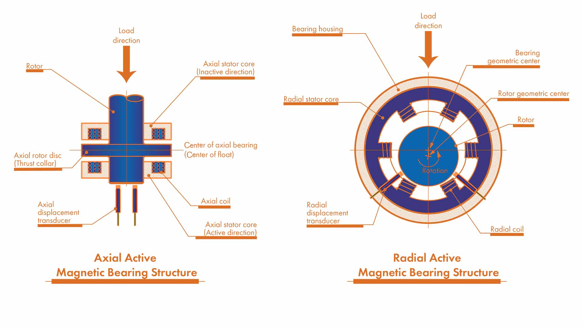
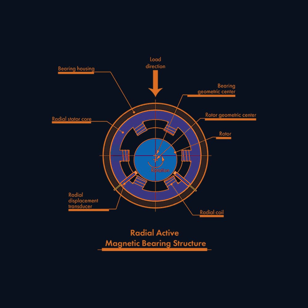
Stages & Roles: Radial, Axial (Thrust) & Auxiliary
Most systems use radial stages for lateral support, an axial stage for end-load control, and auxiliary (catcher) bearings for safe touchdown.
Radial magnetic bearing
Lateral support
Active damping
- Electromagnets + eddy-current probes; PID/state-space control.
- Air-gap ≈ 0.2–1.0 mm class; tight TIR & balance (G 2.5 or better).
- Watch-outs: thermal growth vs. gap, EMI, probe calibration.
- Coating targets: touchdown sleeves & fit seats (not pole faces).
Axial magnetic (active thrust)
End-load control
Bias flux
- Active thrust actuator; probes on thrust runner; real-time force control.
- Homopolar vs. heteropolar bias; check saturation & control authority at max axial load.
- Ride-through/UPS for orderly rundown during trips.
- Coating targets: thrust touchdown rings/sleeves; sensor targets.
Auxiliary (backup/catcher)
Touchdown safety
Heat/energy
- Rated for touchdown energy; clearance set for rare contact.
- Provide lube & heat paths; avoid repeated micro-drops.
- Coatings: hard, low-roughness chrome or Ni-P on sleeves/races; re-balance after processing.
- Watch-outs: cage damage from heat, debris control in clean systems.
Environment → Attributes Matrix
| Environment | Materials / Surfaces | Air-gap & Tolerance | Sealing / Containment | Power / Controls | Notes |
|---|---|---|---|---|---|
| Vacuum / Cleanroom | Low-outgassing metals; coated touchdown sleeves to reduce debris | Tight runout; verify probe calibration after any surface treatment | Non-contact seals; particle control | UPS for orderly rundown; EMI discipline | Avoid coatings that flake or outgas; re-balance |
| Process Gas / Corrosive | Corrosion-resistant housings; chrome/Ni-P on catcher parts | Maintain gap at temp/chem; thermal model | Containment for drop events; purge paths | Control cabinet isolation; sensor compatibility | Validate coating vs. chemistry; don’t alter magnetic paths unintentionally |
| High Speed Compressor | Rotor laminations; hard, low-roughness rub sleeves | Gap ~sub-mm; critical-speed margin; balance grade G 2.5 or better | Gas seals; burst containment | High bandwidth control; ride-through | Touchdown energy sizing for backup bearings |
| Flywheel Energy Storage | Low-loss materials; PM radial + active thrust common | Very small losses; vacuum; thermal stability | Vacuum vessel; crash-safe containment | Redundant sensing & controls | Drop testing & energy dissipation design |
Common Failures & Diagnostics
Rapid Triage

1) Rotor Drop / Touchdown Event
Symptoms
Controller trip, rub noise, temperature spike at catcher, rotor orbit jump in logs.
Likely causes
Power loss (no ride-through), amplifier fault, sensor failure, control instability.
Checks
UPS status, fault tree (amplifier/sensors), orbit and current logs, touchdown energy calc vs. catcher rating.
Non-coating actions
Improve ride-through; redundancy on probes/channels; tune control margins; verify catcher sizing and lube path.
When surface treatments help
Low-roughness, wear-resistant chrome on sleeves/races reduces damage during rare rubs.
2) Control Instability / Whirl
Symptoms
Increasing vibration at certain RPM bands; high actuator current; alarms.
Likely causes
Insufficient phase/gain margin, cross-coupling, rotor mode proximity, sensor noise.
Checks
Bode plots, stability margins, mode shapes, probe alignment and calibration.
Non-coating actions
Re-tune controllers (PID/state-space), adjust filters, alter bearing/plant stiffness.
When surface treatments help
Not primary—control/rotor dynamics dominate.
3) Sensor Drift / Probe Issues
Symptoms
Zero shift, unexpected current bias, false orbit changes.
Likely causes
Temperature drift, target surface change (coating, oxide), EMI, mis-gap.
Checks
Re-calibrate probes; inspect target finish/conductivity; EMI survey; gap check.
Non-coating actions
Thermal stabilization; shielding/grounding; restore target geometry.
When surface treatments help
Stable, smooth, conductive target surfaces can improve signal—validate calibration after coating.
4) Backup Bearing Wear / Overheat
Symptoms
Discoloration, smear marks, cage damage on teardown, high touchdown temperatures.
Likely causes
Under-rated catcher; inadequate lubrication path; repeated micro-drops.
Checks
Touchdown energy calc; lube access; inspect sleeve hardness/finish; event log frequency.
Non-coating actions
Up-rate catcher, improve lube/purge, fix root cause of trips.
When surface treatments help
Hard chrome on sleeves/races improves scuff resistance; verify thickness & balance.
5) Thermal Growth / Air-Gap Rub
Symptoms
Rising current bias, asymmetric gap, rub marks on shields.
Likely causes
Uneven heating, assembly offset, coating thickness asymmetry.
Checks
Thermal model; hot run measurements; concentricity and balance after processing.
Non-coating actions
Improve cooling/ducting; re-center stator/rotor; rebalance.
When surface treatments help
Not a coating problem—focus on geometry and thermal management.
The Big Three: Corrosion, Lubricity, Dimensional Stability
Magnetic gaps are contact-free; coatings apply mainly to backup (catcher) bearings, touchdown sleeves/rings, fit seats, and sensor targets. Coatings don’t replace rotor balance, control tuning, or air-gap discipline.
| Concern | What it means | Non-coating controls (first) | When coatings help | Notes |
|---|---|---|---|---|
| Corrosion resistance | Protect catcher races, sleeves, seats from rust/chemicals | Sealing/containment; purge; compatible materials | Thin dense/micro-cracked chrome or Ni-P on catcher parts | Re-measure geometry; validate chemistry and probe behavior |
| Lubricity | Lower friction/heat during rare touchdown events | Correct catcher type/lube; energy management and rundown logic | Low-roughness or micro-textured chrome on rub sleeves & races | Coatings complement—not replace—catcher design & lube |
| Dimensional stability | Hold air-gap, concentricity, and balance after processing | Tight machining; thermal model; dynamic balance | Controlled-thickness coatings; post-coat metrology & balance | Small thickness shifts change gap, torque, and sensor scale |
Fits, Alignment & Air-Gap (Quick Rules)
-
Concentricity/runout: specify tight TIR for rotor journals, sleeves, and probe targets; measure hot.
-
Air-gap budget: account for thermal growth, assembly tolerances, dynamic deflection; keep minimum gap margin in all states.
-
After coatings: re-measure diameter/roundness, probe scale factor, and re-balance the rotor.
-
Backups: set catcher clearance, preload, and lube path; validate touchdown speed/energy.
Checklist
-
Probe alignment & calibration verified
-
UPS/ride-through tested
-
Post-coat balance report on file
-
Touchdown energy & catcher rating matched
Backup (Catcher) Bearings — Design Snapshot
| Component | Role | Key specs | Coating targets | Notes |
|---|---|---|---|---|
| Rolling catcher bearing | Carries rotor during drop/rundown | High temp/load for short duty; grease path; clearance for thermal | Races/fit seats for corrosion & scuff resistance | Verify post-coat dimensions; don’t over-tighten fits |
| Touchdown sleeve/ring | Sacrificial rub surface at rotor | Hardness; low roughness; roundness and concentricity | Hard chrome or Ni-P for wear & corrosion | Re-balance rotor assembly after processing |
| Seats & housings | Retain catcher, resist fretting | Fit class to prevent creep; seat flatness | Micro-textured chrome to reduce fretting | Clamp sequence; transport vibration control |
Case Snapshots
- Oil-free compressor trip mitigation — Frequent micro-drops during grid sags.
Actions: added ride-through UPS, tuned controller phase margin, hard-chromed touchdown sleeves, verified probe scale.
Outcome: no unplanned drops in 90-day audit; sleeves show only polish marks after test drops. - Vacuum pump contamination control — Probe drift and debris after maintenance.
Actions: polished/recertified probe targets, applied inert micro-cracked chrome to catcher races, added EMI shielding for cables.
Outcome: stable probe zeros; debris counts within spec over 60 days.
Frequently Asked Questions
They can. Conductivity, thickness, and stand-off influence calibration. After coating probe targets, re-calibrate and validate signal linearity.
Avoid anything that bridges laminations or perturbs flux paths. Use only validated processes on magnetic circuits.
AMB systems draw power for control. Use high-efficiency amplifiers and ride-through. Passive/hybrid reduce steady losses but trade controllability.
Very high speeds are feasible because there’s no rolling contact. Limits are set by rotor dynamics, control bandwidth, and containment—design, not friction.

Have a failure photo, sound clip, or spec?
Upload it for a no‑fluff diagnostic checklist. We’ll map symptoms → checks → next actions (and only propose coatings when they’re truly indicated).