Yes. They protect the machine during power loss, trips, or startup/shutdown. Size them for touchdown energy and provide lubrication/heat paths.
Industry Insights
Industry Insights
Magnetic Bearings
Selection, Failures, Fixes & Coatings
What Are Magnetic Bearings?
Magnetic bearings support a rotor with magnetic forces—no physical contact in normal operation.
Active magnetic bearings (AMB) use electromagnets with closed-loop control (sensors + power amplifiers).
Passive designs use permanent magnets or diamagnetic/superconducting effects.
Hybrid systems often pair passive radial support with an active axial stage.
A backup (catcher) bearing carries the rotor during start/stop or faults.
Typical uses: high-speed compressors/blowers (oil-free air/process gas), expanders, vacuum pumps, flywheel energy storage,
turbo-molecular pumps, cleanroom tools, test spindles, cryogenic or caustic processes where no lube and cleanliness are critical.
Selection Cheatsheet (Duty, Air-Gap, Controls, Backup)
- Process & cleanliness: Pick AMB for oil-free/vacuum/clean gas. Validate materials vs. chemistry/temperature.
- Rotor dynamics: Confirm critical speeds, balance grade, and control stability margins (gain/phase) across operating range.
- Air-gap budget: Model thermal growth, bow, and assembly tolerances; preserve minimum gap at all conditions.
- Power strategy: UPS/ride-through needed for orderly rundown; define touchdown speed and energy on backup bearings.
- Controls & sensing: Redundant probes/channels where risk requires; EMI design; proper probe targets/surfaces.
- After coatings: Re-balance rotor; re-verify probe calibration, air-gap, and touchdown geometry; coatings must not perturb magnetic flux paths unexpectedly.
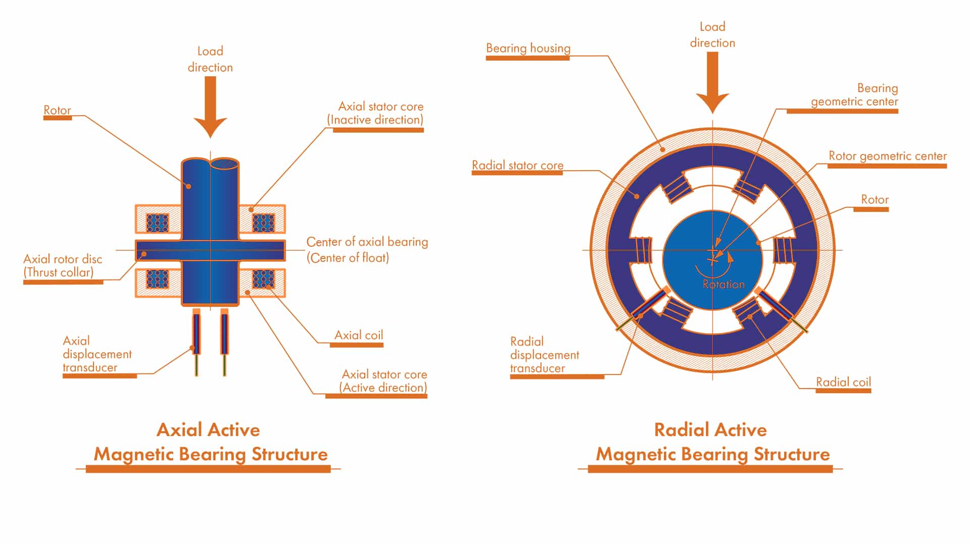
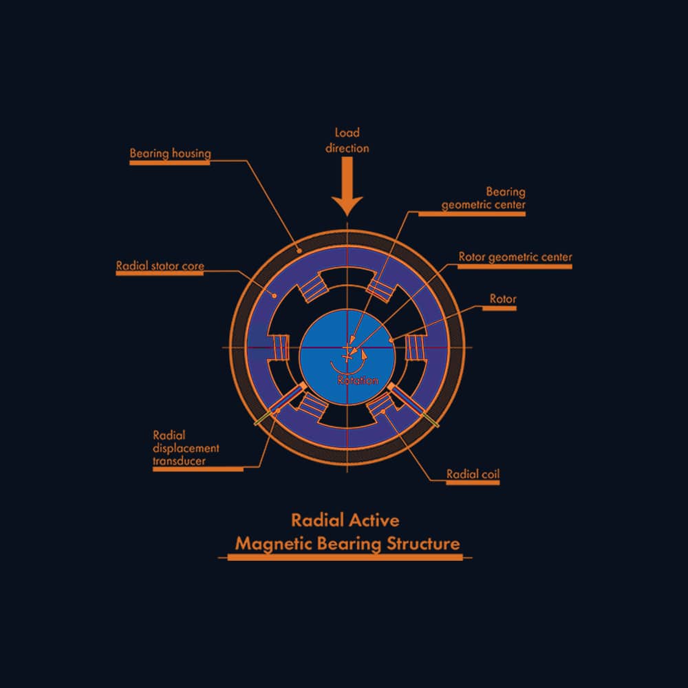
Stages & Roles: Radial, Axial (Thrust) & Auxiliary
Most systems use radial stages for lateral support, an axial stage for end-load control, and auxiliary (catcher) bearings for safe touchdown.
Radial magnetic bearing
Lateral support
Active damping
- Electromagnets + eddy-current probes; PID/state-space control.
- Air-gap ≈ 0.2–1.0 mm class; tight TIR & balance (G 2.5 or better).
- Watch-outs: thermal growth vs. gap, EMI, probe calibration.
- Coating targets: touchdown sleeves & fit seats (not pole faces).
Axial magnetic (active thrust)
End-load control
Bias flux
- Active thrust actuator; probes on thrust runner; real-time force control.
- Homopolar vs. heteropolar bias; check saturation & control authority at max axial load.
- Ride-through/UPS for orderly rundown during trips.
- Coating targets: thrust touchdown rings/sleeves; sensor targets.
Auxiliary (backup/catcher)
Touchdown safety
Heat/energy
- Rated for touchdown energy; clearance set for rare contact.
- Provide lube & heat paths; avoid repeated micro-drops.
- Coatings: hard, low-roughness chrome or Ni-P on sleeves/races; re-balance after processing.
- Watch-outs: cage damage from heat, debris control in clean systems.
Environment → Attributes Matrix
| Environment | Materials / Surfaces | Air-gap & Tolerance | Sealing / Containment | Power / Controls | Notes |
|---|---|---|---|---|---|
| Vacuum / Cleanroom | Low-outgassing metals; coated touchdown sleeves to reduce debris | Tight runout; verify probe calibration after any surface treatment | Non-contact seals; particle control | UPS for orderly rundown; EMI discipline | Avoid coatings that flake or outgas; re-balance |
| Process Gas / Corrosive | Corrosion-resistant housings; chrome/Ni-P on catcher parts | Maintain gap at temp/chem; thermal model | Containment for drop events; purge paths | Control cabinet isolation; sensor compatibility | Validate coating vs. chemistry; don’t alter magnetic paths unintentionally |
| High Speed Compressor | Rotor laminations; hard, low-roughness rub sleeves | Gap ~sub-mm; critical-speed margin; balance grade G 2.5 or better | Gas seals; burst containment | High bandwidth control; ride-through | Touchdown energy sizing for backup bearings |
| Flywheel Energy Storage | Low-loss materials; PM radial + active thrust common | Very small losses; vacuum; thermal stability | Vacuum vessel; crash-safe containment | Redundant sensing & controls | Drop testing & energy dissipation design |
Common Failures & Diagnostics
Rapid Triage
1) Rotor Drop / Touchdown Event
Symptoms
Controller trip, rub noise, temperature spike at catcher, rotor orbit jump in logs.
Likely causes
Power loss (no ride-through), amplifier fault, sensor failure, control instability.
Checks
UPS status, fault tree (amplifier/sensors), orbit and current logs, touchdown energy calc vs. catcher rating.
Non-coating actions
Improve ride-through; redundancy on probes/channels; tune control margins; verify catcher sizing and lube path.
When surface treatments help
Low-roughness, wear-resistant chrome on sleeves/races reduces damage during rare rubs.
2) Control Instability / Whirl
Symptoms
Increasing vibration at certain RPM bands; high actuator current; alarms.
Likely causes
Insufficient phase/gain margin, cross-coupling, rotor mode proximity, sensor noise.
Checks
Bode plots, stability margins, mode shapes, probe alignment and calibration.
Non-coating actions
Re-tune controllers (PID/state-space), adjust filters, alter bearing/plant stiffness.
When surface treatments help
Not primary—control/rotor dynamics dominate.
3) Sensor Drift / Probe Issues
Symptoms
Zero shift, unexpected current bias, false orbit changes.
Likely causes
Temperature drift, target surface change (coating, oxide), EMI, mis-gap.
Checks
Re-calibrate probes; inspect target finish/conductivity; EMI survey; gap check.
Non-coating actions
Thermal stabilization; shielding/grounding; restore target geometry.
When surface treatments help
Stable, smooth, conductive target surfaces can improve signal—validate calibration after coating.
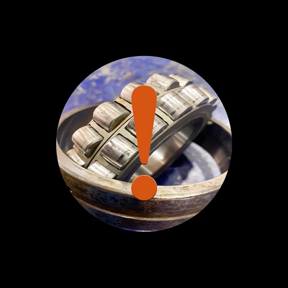
4) Backup Bearing Wear / Overheat
Symptoms
Discoloration, smear marks, cage damage on teardown, high touchdown temperatures.
Likely causes
Under-rated catcher; inadequate lubrication path; repeated micro-drops.
Checks
Touchdown energy calc; lube access; inspect sleeve hardness/finish; event log frequency.
Non-coating actions
Up-rate catcher, improve lube/purge, fix root cause of trips.
When surface treatments help
Hard chrome on sleeves/races improves scuff resistance; verify thickness & balance.
5) Thermal Growth / Air-Gap Rub
Symptoms
Rising current bias, asymmetric gap, rub marks on shields.
Likely causes
Uneven heating, assembly offset, coating thickness asymmetry.
Checks
Thermal model; hot run measurements; concentricity and balance after processing.
Non-coating actions
Improve cooling/ducting; re-center stator/rotor; rebalance.
When surface treatments help
Not a coating problem—focus on geometry and thermal management.
The Big Three: Corrosion, Lubricity, Dimensional Stability
Magnetic gaps are contact-free; coatings apply mainly to backup (catcher) bearings, touchdown sleeves/rings, fit seats, and sensor targets. Coatings don’t replace rotor balance, control tuning, or air-gap discipline.
| Concern | What it means | Non-coating controls (first) | When coatings help | Notes |
|---|---|---|---|---|
| Corrosion resistance | Protect catcher races, sleeves, seats from rust/chemicals | Sealing/containment; purge; compatible materials | Thin dense/micro-cracked chrome or Ni-P on catcher parts | Re-measure geometry; validate chemistry and probe behavior |
| Lubricity | Lower friction/heat during rare touchdown events | Correct catcher type/lube; energy management and rundown logic | Low-roughness or micro-textured chrome on rub sleeves & races | Coatings complement—not replace—catcher design & lube |
| Dimensional stability | Hold air-gap, concentricity, and balance after processing | Tight machining; thermal model; dynamic balance | Controlled-thickness coatings; post-coat metrology & balance | Small thickness shifts change gap, torque, and sensor scale |
Fits, Alignment & Air-Gap (Quick Rules)
-
Concentricity/runout: specify tight TIR for rotor journals, sleeves, and probe targets; measure hot.
-
Air-gap budget: account for thermal growth, assembly tolerances, dynamic deflection; keep minimum gap margin in all states.
-
After coatings: re-measure diameter/roundness, probe scale factor, and re-balance the rotor.
-
Backups: set catcher clearance, preload, and lube path; validate touchdown speed/energy.
Checklist
-
Probe alignment & calibration verified
-
UPS/ride-through tested
-
Post-coat balance report on file
-
Touchdown energy & catcher rating matched
Backup (Catcher) Bearings — Design Snapshot
| Component | Role | Key specs | Coating targets | Notes |
|---|---|---|---|---|
| Rolling catcher bearing | Carries rotor during drop/rundown | High temp/load for short duty; grease path; clearance for thermal | Races/fit seats for corrosion & scuff resistance | Verify post-coat dimensions; don’t over-tighten fits |
| Touchdown sleeve/ring | Sacrificial rub surface at rotor | Hardness; low roughness; roundness and concentricity | Hard chrome or Ni-P for wear & corrosion | Re-balance rotor assembly after processing |
| Seats & housings | Retain catcher, resist fretting | Fit class to prevent creep; seat flatness | Micro-textured chrome to reduce fretting | Clamp sequence; transport vibration control |
Case Snapshots
- Oil-free compressor trip mitigation — Frequent micro-drops during grid sags.
Actions: added ride-through UPS, tuned controller phase margin, hard-chromed touchdown sleeves, verified probe scale.
Outcome: no unplanned drops in 90-day audit; sleeves show only polish marks after test drops. - Vacuum pump contamination control — Probe drift and debris after maintenance.
Actions: polished/recertified probe targets, applied inert micro-cracked chrome to catcher races, added EMI shielding for cables.
Outcome: stable probe zeros; debris counts within spec over 60 days.
Frequently Asked Questions
They can. Conductivity, thickness, and stand-off influence calibration. After coating probe targets, re-calibrate and validate signal linearity.
Avoid anything that bridges laminations or perturbs flux paths. Use only validated processes on magnetic circuits.
AMB systems draw power for control. Use high-efficiency amplifiers and ride-through. Passive/hybrid reduce steady losses but trade controllability.
Very high speeds are feasible because there’s no rolling contact. Limits are set by rotor dynamics, control bandwidth, and containment—design, not friction.
Contact Armoloy
Have a failure photo, sound clip, or spec? Upload it and we’ll assess the issue and outline recommended next steps.
Request Information